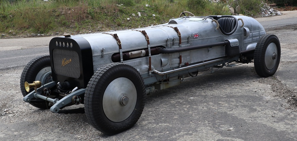
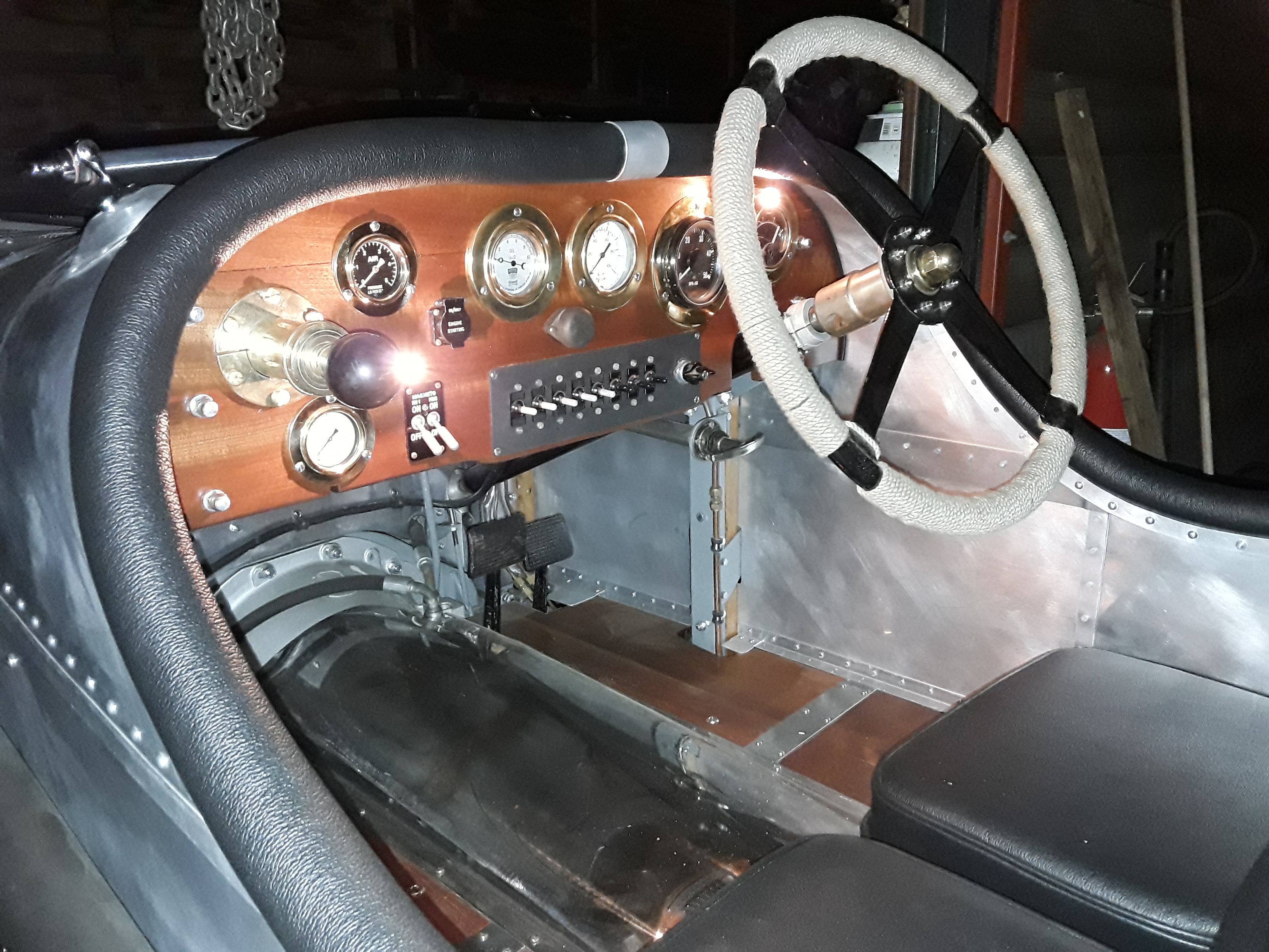
I had been collecting the gauges and switches etc.for the Flyers cockpit right from the start of the idea ,some were found on ebay some had been laying about in the shed left over from other projects ,others like the fuel air pressure pump I made using an old oil gun dispenser and a non return valve as the fuel system only runs on about 2 lb per sq ins it works fine with a pump at about one minute intervals when the tank is full and about every 5 minutes when half full .
The ignition switches are genuine ex.Air ministry NOS and would have been fitted to many different aero planes and not only Spitfires as the people who have them for sale would have you believe. The start button and cover the flick switches and volt meter are all ex. Air Ministry .
As mentioned elsewhere I believe the Ki gas pump to a genuine Spitfire fitting.
The tacho display is from a CVRT as are the radiators and is driven electrically from a generator running off the front of the off side camshaft. One mistake I did make ,that I will put right in the fullness of time is that I ran the wires from the taco generator in the same conduit as the spark booster coil wire so that when the booster is switched on it causes the rev counter to flick about without the engine even running, but that does not cause any particular problem as the booster coil is switched off as soon as the engine starts.
Most of the brass bezels and bulb holders I had on the shelf apart a matching bezel for the rev counter that was cut from sheet brass.
The Totham Flyer Cockpit Layout

1. Main Radiator cooling fans X 3. 2. Engine and Transmission oil cooling fan. 3. Spark Booster Coil. 4. Oil priming Pump. 5. Spare. 6. Spare. 7. Main Battery Isolator. 8. Engine Ki Gas Priming Pump. 9. Engine R.P.M. counter. 10. Start Battery Voltage 24 V. | I11. Battery Charge indicator. 12. Engine Main Oil pressure. 13. Secondary Oil pressure to Camshafts. 14. Horn. 15. Fuel Tank air Pressure. 16. Transmission Neutral indicator. 17. Fuel air pressure Pump. 18. Engine Radiator Temperature. 19. Twin Magneto Switches. 20. Engine Start button.
|
In addition to the above I have now fitted a CO2 Fire extinguisher system controlled from inside on the right hand side of the cockpit near the Ki Gas pump, and also a Fuel tank air pressure dump valve on the near side.
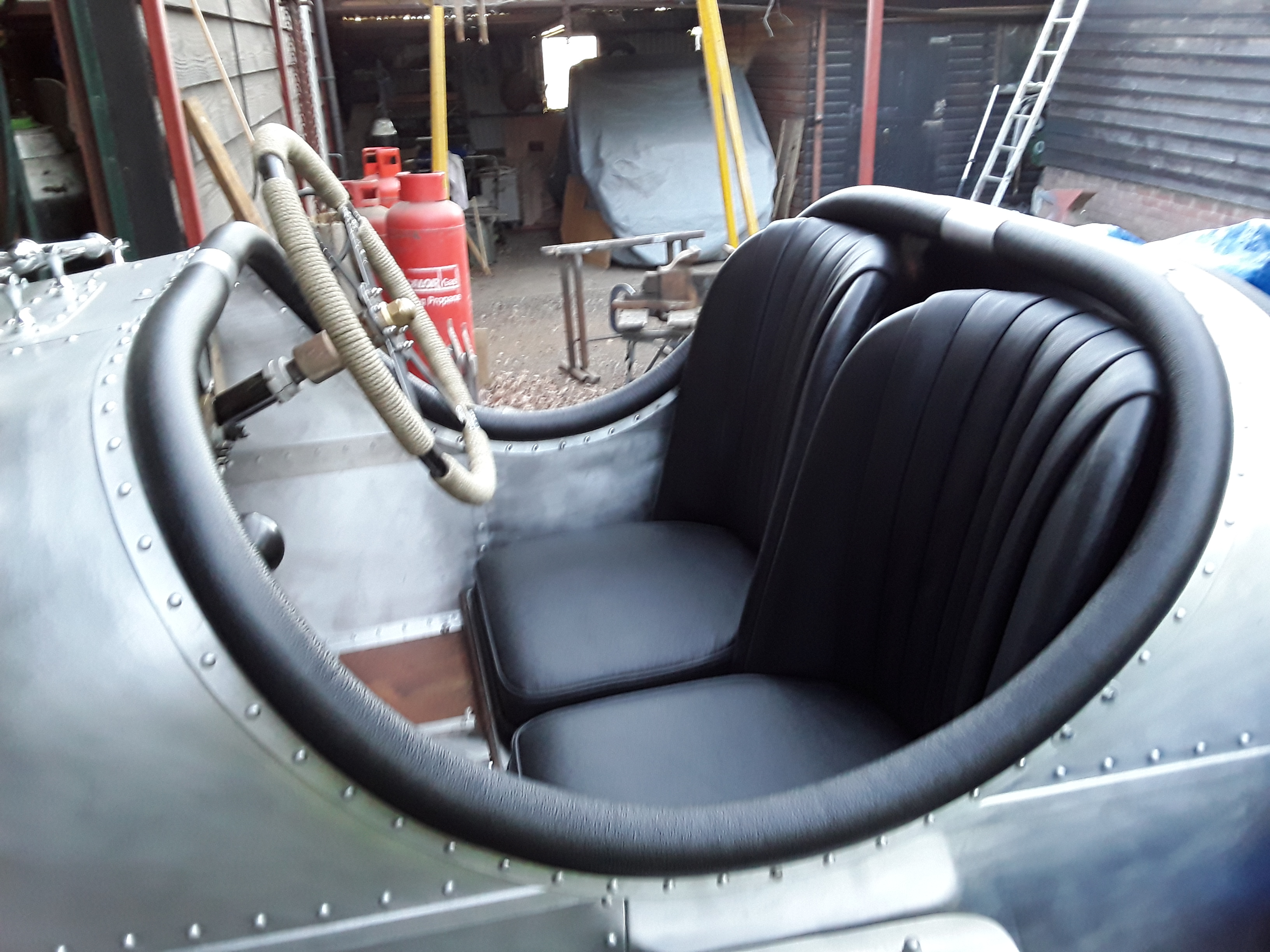
One other thing that I need to mention here are the seats , they were found in a shed not 100 yards from were I was building the Flyer , the covers were a bit tatty but as I was not sure how the vehicle was going to turn out I thought I may leave them as they were ,but as the project progressed it was obvious that they would need to be re upholstered. Step in a life long friend of mine Pud who along with his wife Sue offered to re trim them in black leather for me as part of the project if I supplied the hide, and a very nice job they made too. There was enough hide left over for me to trim the cockpit edges.
Unfortunately although he saw the Flyer finished and running my friend Pud passed away suddenly before he was able to see it moving under its own power.
|
|
Below I have given a starting check list from cold , I still have a copy on hand when starting the Totham Flyer as it is very easy to forget something in the excitement , I still get a flood of adrenalin when I start the engine in the vehicle.
Checks Outside the Vehicle Checks Inside the Vehicle
|
|
It is good practice to the check mag drop by switching one magneto off while the engine is running at about 1000 rpm off load the rpm should drop by about 100 if the magneto is functioning correctly. Then put it back on and switch the other mag off too check that one also. This test comes from aero engine procedure but is all ways worth doing to keep an eye on things.
To stop the car, come to a stand still and apply the hand brake before selecting the neutral position then check water temperature and oil pressure. To stop engine all I do is flick both ignition switches to off ,Check battery voltage and turn the main 24 volt battery isolator to the off position .Then go round the outside of the vehicle and dump the fuel tank air pressure close the main fuel cock and release the fuel tank cap.
On the first outing at the test track I drove the vehicle up to 70 mph at 1200 rpm and it steers and stops better than I could have hoped. I have a few small jobs to do over this winter and then my mate Graham and I will be testing again in the spring of 2020.


