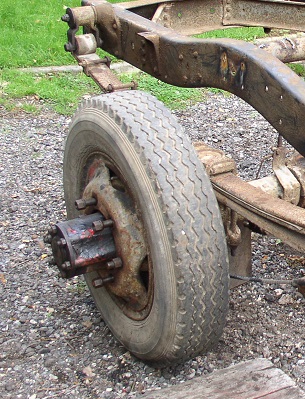
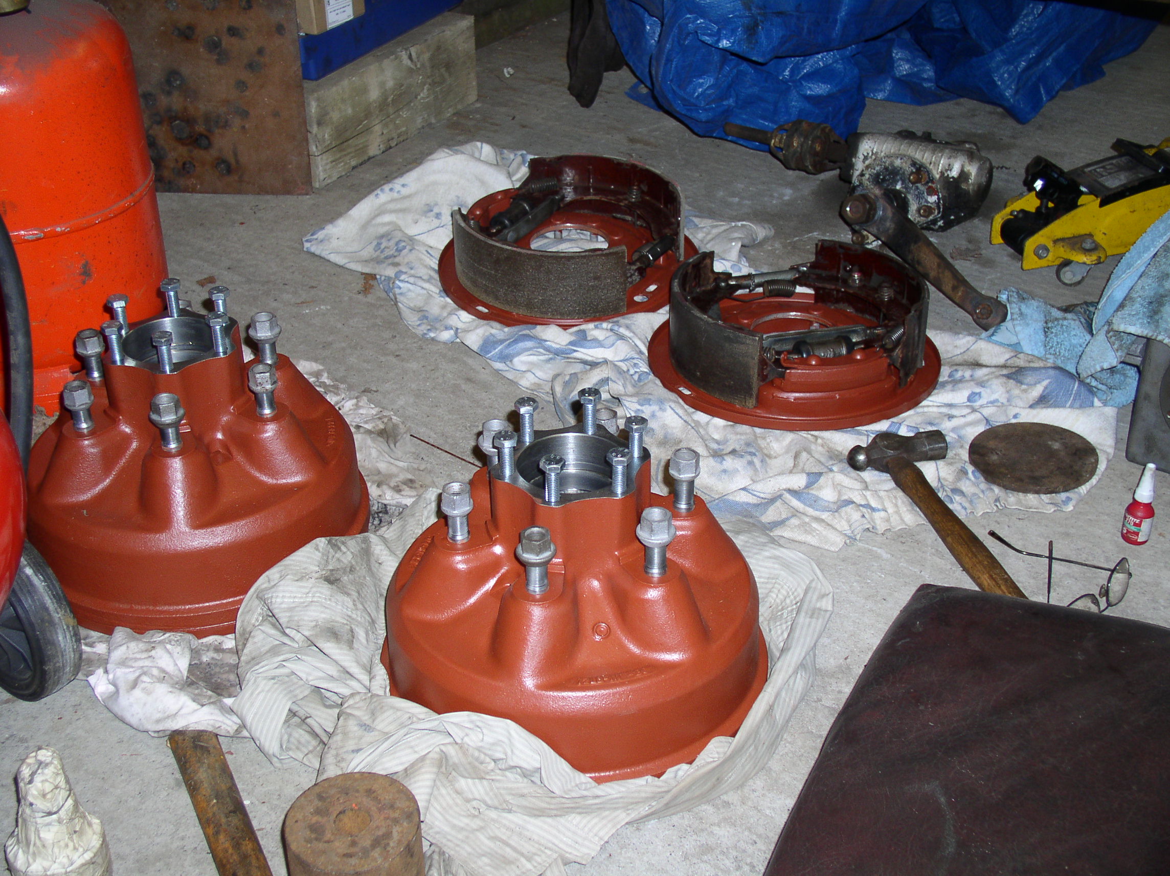
When I got round to inspecting the ford axles it became clear that they were in such good condition that with a bit of alteration they would be as good or better than any thing I would be able to find. The differential was the heavy duty 5-1 ratio that was standard for the 3 ton tipper version of the truck, and on close inspection showed no wear of any kind plus the half shafts being 1 1/2 ins in diameter looked like they would be man enough for the job.
The front axle king pins were also in perfect condition ,and all four brake drums were unmarked with perfect shoes and springs. unfortunately the slave cylinders although they looked like they would be usable, the front two proved to leak slightly so I did have them all professionally sleeved with stainless steel and new seals fitted.
The problems started when I put a tape measure across them and it was clear that both axles were too wide, now that the body was going to be considerably narrower, also the rear axle and hubs were set up for twin rear wheels.
The existing wheels I put to one side for the time being because they were 16 ins and to complete the look I wanted I would be needing 20 ins and a narrower section .
The front axle proved to be of little trouble, I simply had to cut and remove 10 ins from the center allowing for the joggle and re-weld back together dead straight and in the same plane.Then build and weld in position plinths and damper mounts to bring everything into line .
The brake drums etc were cleaned and the bearings checked and reassembled It would be a further six months before I found out about the slave cylinder leaks,
I had also worked out that if I was lucky I would be able to maintain the original steering geometry and only have to make a new drag link, In the end I also had to make a new track rod with a step in it to clear the Meteor sump.
Front Axle Gallery
One strange problem that arose later in the build relating to the front brakes, I found it impossible to bleed them satisfactory using the original ford brake pipe arrangement behind the back plates which had the bleed nipple at the lowest point, by changing it to the top as is the more usual way, I had no further problems and was able to remove the air and get a sound brake pedal with ease, I have since been able to look at the factory manual for the system and it was correct to the book before I changed it.
The rear axle turned out to be quite a large machining job and took a lot longer than I expected it to.
| The cause of all my problems with the rear axle can be seen in this photo,As the vehicle was original configured it was fitted with twin rear wheels and as such the hub was extended to carry the bearings to support the outboard load. The drive half shafts were on the outboard end of these . This would entail machining away most of the housing and boring out the drums to shift the bearings inboard. This done the next problem was getting the front and rear track the same some vehicles have been produced with the front and rear OA wheel measurements different but that was not what I wanted for The Flyer |
|
|
The next task involved re machining the ends of the rear axle side tubes to carry the bearings in the new positions to suit the hubs, but my lathe was not even remotely long enough ,so I hatched a plan to kill two birds with one stone .
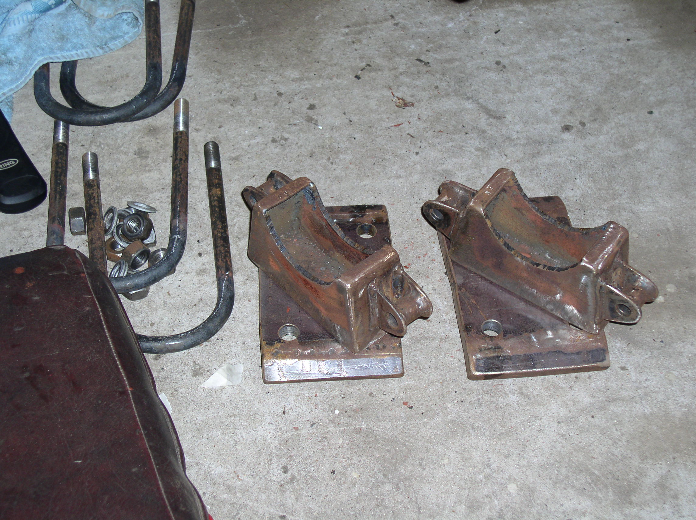
I started by cutting through the side tubes in the position where the spring mounting pedestals were going to be welded, so that they gave the join extra strength mid way between the differential and the brake back plates . This now meant I could do the machining on the outboard ends, and at the same time make up spacers to weld in the gap to extend the new hub positions out to the OA measurement I required to bring the hubs into line and this also enabled me to use the original half shafts without cutting and welding them as I know from experience is seldom satisfactory.
Rear axle Gallery
All this work and really all I did was to turn a twin wheel axle into a single wheel axle.
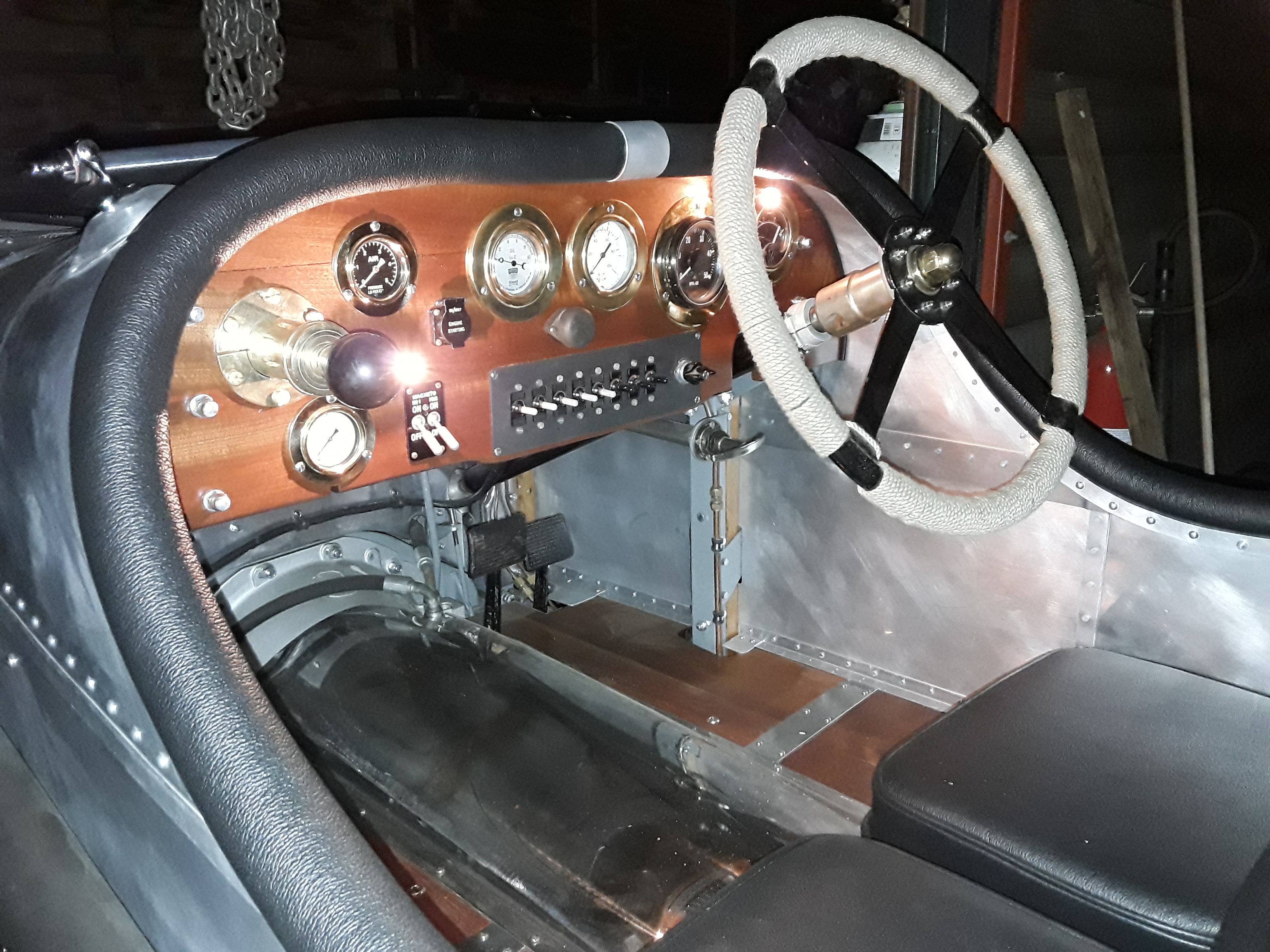
The following week was talking about building the Flyer to a scrap man friend of mine and saying that I was looking for some period parts to build into it when he said the magic words, come with me , we went round the back of some old sheds and there in the nettles and brambles were the rotting remains of three WW11 Thornycroft road sweepers , all beyond restoration but with many parts that would be perfect for my purpose , £50 for all I could unbolt , two days later I had a heap of useful parts including pedal boxes, steering wheel a pair of huge hand brake leavers and their mounts, not to mention a hoard of small fittings etc.
Image Gallery
As can be seen from the photos above I built in twin brake master cylinders so that I could use a bias balance bar but as it has turned out having the bar central works fine having said that I haven't tried to brake hard in the rain yet.
I also changed the master cylinders in the photo they are series 3 Land Rover but they proved to be a bit to big in the bore and I had no movement in the pedal what so ever by going to series 2 they worked fine , I ended up moving the fluid reservoirs and made a dual one fitted up on the bulkhead to make it easier to top them up. I did eventually fit two external brake levers on the one shaft to use one as a gear selector.
At this point I was about 20 months into the project and was happy how it was going so far
